前回はハードウェアを組みましたが、いよいよソフトウェアに突入します。
ソフトウェア
ライブラリ導入
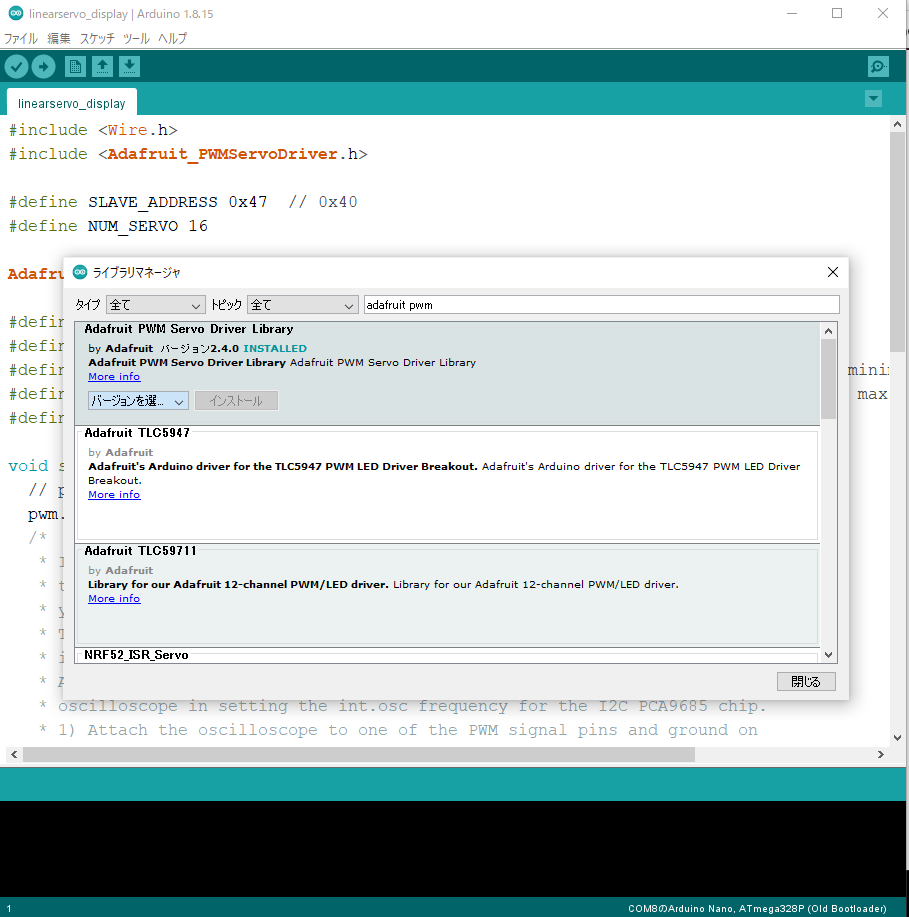
PCA9685を制御するため、今回はAdafruitから提供されているPCA9685用ライブラリをインストールします。
インストールはArduino IDEから簡単にできます。手順は以下の通りです。
- Arduino IDEを起動
- タブの スケッチ >> ライブラリをインクルード >> ライブラリを管理.. と選択してライブラリマネージャを開く
- 検索欄に「adafruit pwm」と入力して、「Adafruit PWM Servo Driver Library」をインストール

無事にインストールされたら準備完了。ソースコードも書き込めるようになります。
ソースコード
では、Arduino用のスケッチ(ソースコード)を見てみましょう。
|
1 2 3 4 5 6 7 8 9 10 11 12 13 14 15 16 17 18 19 20 21 22 23 24 25 26 27 28 29 30 31 32 33 34 35 36 37 38 39 40 41 42 43 44 45 46 47 48 49 50 51 52 53 54 55 56 57 |
#include <Wire.h> #include <Adafruit_PWMServoDriver.h> #define SLAVE_ADDRESS 0x40 #define NUM_SERVO 16 Adafruit_PWMServoDriver pwm = Adafruit_PWMServoDriver(SLAVE_ADDRESS); #define SERVOMIN 150 // This is the 'minimum' pulse length count (out of 4096) #define SERVOMAX 600 // This is the 'maximum' pulse length count (out of 4096) #define USMIN 600 // This is the rounded 'minimum' microsecond length based on the minimum pulse of 150 #define USMAX 2400 // This is the rounded 'maximum' microsecond length based on the maximum pulse of 600 #define SERVO_FREQ 50 // Analog servos run at ~50 Hz updates void setup() { // put your setup code here, to run once: pwm.begin(); // set the module frequency pwm.setOscillatorFrequency(27000000); pwm.setPWMFreq(SERVO_FREQ); // Analog servos run at ~50 Hz updates delay(10); } void loop() { static uint8_t servonum = 0; // put your main code here, to run repeatedly: for (uint16_t pulselen = SERVOMIN; pulselen < SERVOMAX; pulselen++) { pwm.setPWM(servonum, 0, pulselen); } delay(500); for (uint16_t pulselen = SERVOMAX; pulselen > SERVOMIN; pulselen--) { pwm.setPWM(servonum, 0, pulselen); } delay(500); // Drive each servo one at a time using writeMicroseconds(), it's not precise due to calculation rounding! // The writeMicroseconds() function is used to mimic the Arduino Servo library writeMicroseconds() behavior. for (uint16_t microsec = USMIN; microsec < USMAX; microsec++) { pwm.writeMicroseconds(servonum, microsec); } delay(500); for (uint16_t microsec = USMAX; microsec > USMIN; microsec--) { pwm.writeMicroseconds(servonum, microsec); } delay(500); servonum++; if (servonum > NUM_SERVO - 1) servonum = 0; } |
中の処理を上から順番に開設していきます。
まずはライブラリのインクルードです。ここではAdafruitのライブラリに加え、ArduinoのI2C通信用ライブラリ(Wire.h)を入れています。なお、Wire.hはデフォルトでインストールされています。
|
1 2 |
#include <Wire.h> #include <Adafruit_PWMServoDriver.h> |
次に、定数とPCA9685制御ライブラリのインスタンスを記述します。
定数はI2Cアドレス(SLAVE_ADDRESS)とモーターの数(NUM_SERVO)、PWMのパルス秒数と周波数を定義しています。PWMのパルス秒数は、12bit分解能でのHI状態のパルス数(SERVOMIN/SERVOMAX)とマイクロ秒で直接指定するもの(USMIN/MAX)の2種類があります。
また、Adafruit_PWMServoDriverという型のインスタンスを定義します。スレーブアドレスを引数に初期化するもので、このインスタンスからサーボを制御します。
|
1 2 3 4 5 6 7 8 9 10 |
#define SLAVE_ADDRESS 0x40 #define NUM_SERVO 16 #define SERVOMIN 150 // This is the 'minimum' pulse length count (out of 4096) #define SERVOMAX 600 // This is the 'maximum' pulse length count (out of 4096) #define USMIN 600 // This is the rounded 'minimum' microsecond length based on the minimum pulse of 150 #define USMAX 2400 // This is the rounded 'maximum' microsecond length based on the maximum pulse of 600 #define SERVO_FREQ 50 // Analog servos run at ~50 Hz updates Adafruit_PWMServoDriver pwm = Adafruit_PWMServoDriver(SLAVE_ADDRESS); |
setup関数で初期設定を行います。
|
1 2 3 4 5 6 7 8 9 10 |
void setup() { // put your setup code here, to run once: pwm.begin(); // set the module frequency pwm.setOscillatorFrequency(27000000); pwm.setPWMFreq(SERVO_FREQ); // Analog servos run at ~50 Hz updates delay(10); } |
pwm.begin()は、PCA9685とのI2C通信を開始するもので、これを実行しないとサーボモーターの制御ができません。
setOscillatorFrequencyとsetPWMFreqはどちらも周波数の設定で使いますが、前者は内部クロックの周波数、後者はPWM制御の周波数を決めるものです。内部クロックはデフォルトで25MHzと設定されているので、調整が必要なければsetOscillatorFrequencyを呼び出す必要はありません。
そして、メイン処理(loop関数)でモーターの制御を行います。
|
1 2 3 4 5 6 7 8 9 10 11 12 13 14 15 16 17 18 19 20 21 |
void loop() { static uint8_t servonum = 0; // put your main code here, to run repeatedly: for (uint16_t pulselen = SERVOMIN; pulselen < SERVOMAX; pulselen++) { pwm.setPWM(servonum, 0, pulselen); } //(省略...) // Drive each servo one at a time using writeMicroseconds(), it's not precise due to calculation rounding! // The writeMicroseconds() function is used to mimic the Arduino Servo library writeMicroseconds() behavior. for (uint16_t microsec = USMIN; microsec < USMAX; microsec++) { pwm.writeMicroseconds(servonum, microsec); } //(省略...) servonum++; if (servonum > NUM_SERVO - 1) servonum = 0; } |
モーターを動かす関数はsetPWMとwriteMicrosecondsの2種類あります。
- setPWM(ch, 0, pulse): 指定のピン(ch)のPWM信号を決定します。2番目の引数でONのタイミング、3番目の引数でOFFのタイミングを指定します。今回はすぐにONにして、pulse後にOFFへ変えます。
- writeMicroseconds(ch, us): 指定のピン(ch)のPWM信号をマイクロ秒(us)で決定します。
今回は2種類を順番に使ってみました。動き方はどちらも一緒(モーターを最小角から最大角まで動かすもの)ですが、writeMicrosecondsのほうがより細かく制御できます。
また、static変数のservonumをインクリメントしていくことで、動かすモーターを順番に切り替えています。
これをArduinoに書き込めばPCA9685でサーボモーターが動かせるようになります。
サンプル
PCA9685を使えば一度にたくさんのサーボモーター(最大662個)を動かすことができます。
デフォルトのServoライブラリでも12個(Arduino UNO)まで同時に動かせますが、IOピンも占有してしまうので、I2C通信ピンだけで数多くのモーターを動かせて、ほかのピンを別の目的に利用できます。
Revetroniqueでは、PCA9685を使ってロボットアームを作っていました。
ちなみに、アーム用の部品はAmazonで購入しました。
結構組み立てに苦労したので、いずれ別記事で紹介したいと思います。
さらに応用して、こんな作品も制作したりしてます。
サーボモーターをたくさん使いたい方は、ぜひ使ってみてください。
参考
以下のページを参考にしました。
また、公式リファレンスでライブラリの使い方も参照できます。


